 English
 简体中文
简体中文How much does the arc design of the synchronous belt tooth shape affect the meshing stability
As an important power transmission element in modern mechanical transmission systems, the performance of the synchronization belt is directly related to the operating efficiency and stability of the equipment. Among many design parameters, the design of tooth shape is particularly critical, especially the arc design of the synchronous belt tooth shape has a profound impact on the stability during the meshing process.
Basic concepts of tooth arc design
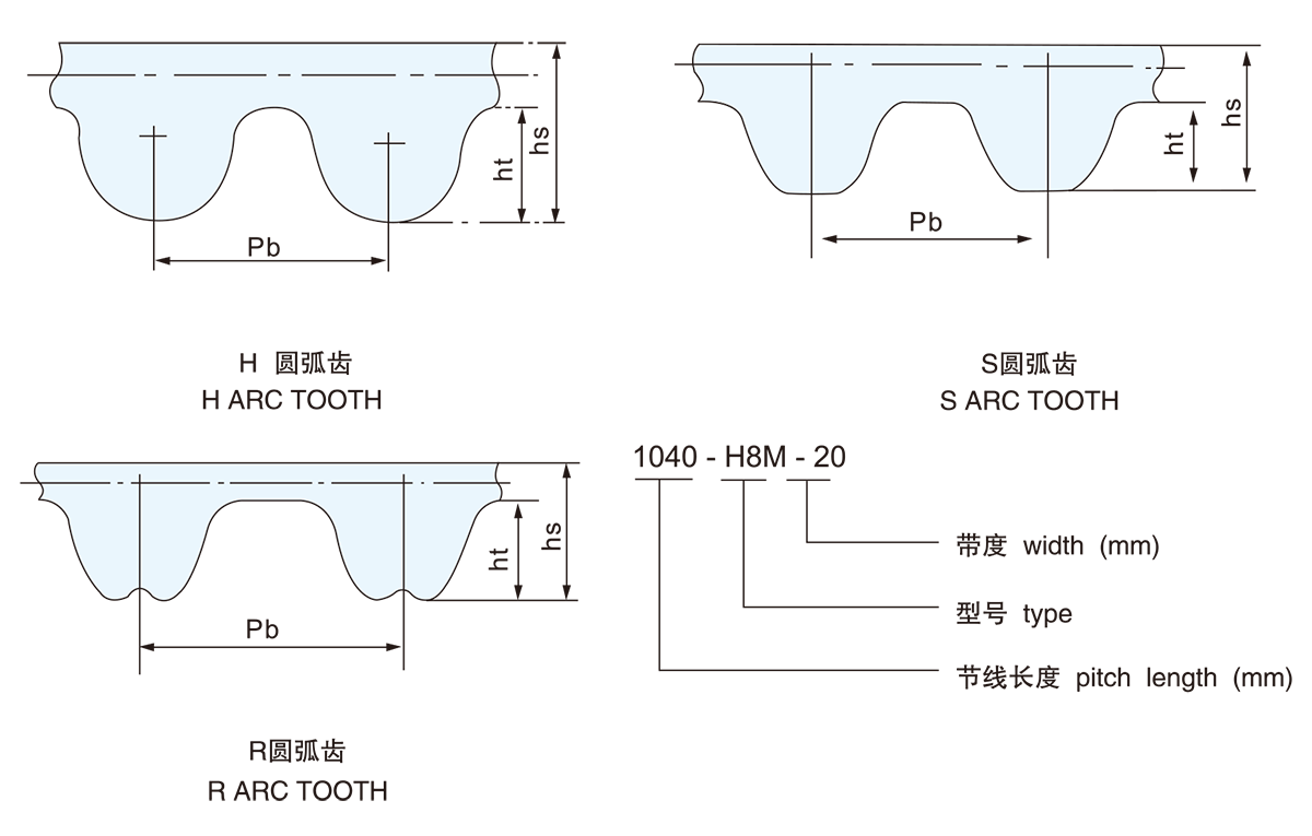
The tooth shapes of the synchronization belt are usually divided into trapezoidal teeth, arc teeth and a variety of improved tooth shapes. Traditional trapezoidal teeth are widely used because of their simple manufacturing and low cost, but there are obvious angular changes at the top and roots of the teeth, resulting in concentrated contact stress during meshing. The arc-tooth synchronization belt adopts a tooth arc design, that is, the tooth profile transitions through the curve, reducing sharp edges and angles, making the tooth surface contact more continuous and smooth.
Optimization of tooth arc to meshing contact mode
The meshing process is the process of physical contact between the synchronous belt and the gear meshing groove to transmit power. The arc design makes the contact area between the synchronous belt tooth profile and the gear tooth shape wider, and the contact line changes from single point or single line contact to surface contact, reducing the peak of contact stress. The smooth arc transition reduces impact load and vibration during engagement, thereby improving the smoothness and accuracy of the transmission.

Improved stress distribution uniformity
The arc tooth design eliminates the stress concentration phenomenon between the root and the tooth top in the traditional tooth shape through curve transition. Stress concentration not only easily causes tooth wear and fatigue cracks, but also leads to increased vibration and noise during the transmission process. The radian design allows the transfer load to be evenly distributed along the tooth surface, reducing local stress peaks, reducing material fatigue, and significantly extending the service life of the synchronization belt.
Improvement of transmission efficiency and noise control
Meshing stability directly correlates transmission efficiency and noise levels. The continuous transition and wide contact area brought by the tooth arc design make the power transmission more stable and reduce sliding friction and impact. Friction loss decreases and energy transfer efficiency improves. At the same time, vibration and noise are significantly reduced due to the reduction of impact load, meeting the strict requirements of modern industry for equipment low noise and low vibration.
Performance advantages under dynamic load
In industrial applications, synchronous belts often face complex operating conditions such as frequent start-stop and variable speed operation. The arc teeth design can effectively buffer the inter-tooth meshing impact, ensuring that the synchronous belt maintains stable meshing under high speed and variable load conditions. The arc design of the tooth shape optimizes the geometric parameters of the tooth profile, improves the meshing trajectory between the tooth and the gear teeth, and reduces vibration and wear caused by dynamic impact loads.
The impact of manufacturing process on the realization of arc design
The tooth arc design puts higher requirements on manufacturing accuracy. High-precision tooth shape processing ensures the accuracy and consistency of the tooth profile curve, which directly affects the precision of meshing. Modern CNC machining and mold technology enables the precise manufacturing of complex arc-shaped tooth profiles, which promotes the improvement of arc-tooth synchronization belt performance. The coordinated development of design optimization and manufacturing processes is the key to achieving an ideal tooth arc.
|
Gear Code |
Type |
Pb Pitch |
Ht Tooth height |
Hs Belt thickness |
Detail |
|
H |
2M |
2 |
0.75 |
1.36 |
|
|
3M |
3 |
1.22 |
2.4 |
||
|
5M |
5 |
2.06 |
3.8 |
||
|
8M |
8 |
3.36 |
6.00 |
||
|
14M |
14 |
6.02 |
10.00 |
||
|
20M |
20 |
8.4 |
13.20 |
Detail |
|
|
S |
S2M |
2 |
0.76 |
1.36 |
Detail |
|
S3M |
3 |
1.14 |
2.20 |
||
|
S4.5M |
4.5 |
1.71 |
2.81 |
||
|
S5M |
5 |
1.91 |
3.4 |
||
|
S8M |
8 |
3.05 |
5.3 |
||
|
S14M |
14 |
5.3 |
10.2 |
||
|
R |
R3M |
3 |
1.15 |
1.9 |
|
|
R5M |
5 |
1.95 |
3.5 |
||
|
R8M |
8 |
3.2 |
5.5 |
||
|
R14M |
14 |
6.00 |
10 |
Detail |
Hot Products
-
 View More
-
 View More
V-belt For Industry
-
 View More
T Type Industry Rubber Synchronous Belt
-
 View More
Toothed wedge belt
-
 View More
Thickened timing belt
-
 View More
Open Timing Belt
-
 View More
Automotive V-belt
-
 View More
Rubber Flat Belt
-
 View More
Ribbed Belt
-
 View More
Synchronous Pulley
-
 View More
Arc tooth industrial rubber synchronous belt
-
View More
Automotive timing belt

Do you have a question? Feel free to contact!
Copyright © Ningbo GUL TZ Rubber Belt Co., Ltd. All rights reserved.

OEM Rubber Driving belts Manufacturers